
Silhouette Pyramid for
Wave Particles
This is a fast wave generation method designed for creating wave particles due to object interaction with a fluid surface. Note that the algorithm is designed for current GPU architectures, and it favors speed over accuracy.
We start with a low resolution silhouette of the interacting object as seen from an orthographic top view. The floating point color values in this image represent the object silhouette, as well as wave effects (wave volumes) of the faces of the object. The aim of the silhouette pyramid method is to distribute wave effects to the nearest silhouette boundary pixels and compute wave directions at these locations. The resulting image is used to generate wave particles due to object motion in the fluid.
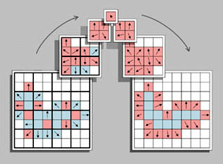
The silhouette pyramid algorithm uses multiple iterations to convert the initial low resolution silhouette image to lower and lower resolutions averaging wave effects and directions. Then, again using multiple iterations, the averaged values in the lower resolution images are used to smooth directions and distribute wave effects while moving back to higher resolutions. The above figure shows an overview of the algorithm. The steps of the silhouette pyramid method are explained in the following:
Step 1:
We begin with drawing a low resolution silhouette of the object on a floating point texture buffer. Remember that we will generate wave particles from each pixel of the silhouette boundary, so we try to keep the texture resolution as low as possible (4x4 to 32x32 should be enough for a single object). We discard all the fragments outside the fluid, and write the depth (in fluid) and vertical component of the surface normal (normal-z) onto two separate color channels. Note that if we do not discard the fragments outside the fluid volume or if all fragments are inside the fluid volume (the object is fully submerged), all normal-z values would be positive. We will use the sign of normal-z to identify if the object is fully submerged at any pixel location.
Step 2:
We copy this texture onto another texture buffer with the same size, and draw each face as a point writing the wave effect of the face. When writing the wave effect, we check the normal-z and depth values on the corresponding pixel such that:
If the normal-z is positive (this means that the object is fully submerged at this pixel location), we compare the depth of the face point to the surface depth value at the pixel (you may use some bias here). If the depth of the point is larger than the surface depth, the face is not on top of the object and the wave effect will be distributed (indirect wave), otherwise the face is on top of the surface and the wave effect will be direct.
If the normal-z is negative, the object is partially submerged at this pixel location and the wave effect is indirect.
We record the direct and indirect wave effects on separate channels, and combine them with additive blending so that if two face points correspond to the same pixel, both values are added. The other two components of this texture will keep the depth and the normal-z values of the previous texture.
Step 3:
Now that our silhouette and wave effects are ready, we draw the texture from the previous step onto another texture buffer with the same size. This time our task is to identify boundary pixels and assign boundary directions. For each silhouette pixel we copy the wave effect channels and check the four neighbors of the pixel. There are two alternatives for picking the boundary pixel: inner boundary (pixels on the object silhouette) and outer boundary (neighboring pixels to object silhouette). When using inner boundaries, if any one of the four neighbors of a silhouette pixel is empty, this pixel is on the boundary and we assign a boundary direction. The boundary direction at this point is simply the sum of all directions towards empty neighboring pixels. Note that this direction can be a zero vector for some boundary pixels (if empty neighbors are on either side of the pixel). When using outer boundaries, the boundary pixels are empty pixels with a non-empty 4-neighbor pixel, and the boundary directions are set as the sum of all directions towards non-empty boundaries. Note that when using inner boundaries, the generated waves should be moved outside the silhouette using the final boundary directions, so that the generated waves do not coincide with the object silhouette.
If the normal-z value at this pixel is positive (object is fully submerged at the pixel location), we invert the direction since the direction of the waves generated at this point should be inwards from the boundary (see Wave Particles paper Figure 8).
Step 4:
This step is repeated a number of times to smooth the directions and distribute the indirect wave effects. We draw the previous texture onto another texture buffer with half the width and height. At each pixel of this new texture, we look at the corresponding four pixels of the previous texture. We identify how many of these four pixels are on the silhouette boundary and write it on a color channel. If any of the four pixels is on the boundary, this pixel on the new texture is also considered a boundary pixel. The final direction vector is taken as the sum all four direction vectors, and the wave effect it the sum of the wave effect from all non-boundary pixels. We repeat this step a number of times (usually until the final texture size is 1x1).
Step 5:
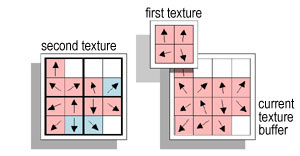
Now we move back to higher resolutions by repeating this step a number of times. This time we use two textures from the previous steps. The first texture is the immediate previous texture (similar to the previous steps). Since we are moving to a higher resolution, the texture buffer of this step has twice the width and height of the first texture. The second texture is a previous texture from an earlier step, which has the same size with the current texture buffer (see figure below).
At each pixel we compute the directions and indirect wave effects using the two textures. The direction is simply the average of the corresponding directions in the two textures. The indirect wave effect is computed only on the pixels identified as silhouette boundary on the second texture. The value of the indirect wave effect is the sum of the wave effect value on the second texture and the wave effect value on the first texture divided by the number of boundary pixels (one to four) recorded on the first texture. Through this procedure, each boundary pixel keeps half of its indirect wave effect, and distributes the other half to neighboring boundary pixels.
We repeat this step until we reach the original silhouette resolution. When we reach the original silhouette resolution, we also record the direct wave effect on this texture.
Step 6:
We copy the final texture from the previous step to the main memory and generate wave particles on the CPU using this texture. To find the dispersion angle at any pixel, we look at the neighboring boundary points and compute the angular difference of the wave directions from the wave direction at the current pixel. The average of these differences is taken as the dispersion angle.
<< Go back to the wave particles page.